NEXTEC Work Light LED Array
While experimenting with 5V power delivery over USB-C, I thought of an experiment that will utilize my new understanding of computer cooling fan tachometer wire. For this experiment I will need a light source in addition to the fan itself. I wanted a nice and bright array of many LEDs, and preferably something already set up to run at around 12V so I wouldn't have to add current-limiting resistors. A few years ago, I took apart a Sears Craftsman NEXTEC work light for its battery compartment. Now it is the LEDs turn to shine. That battery pack used three lithium 18650 cells in series, so it is in the right voltage range.
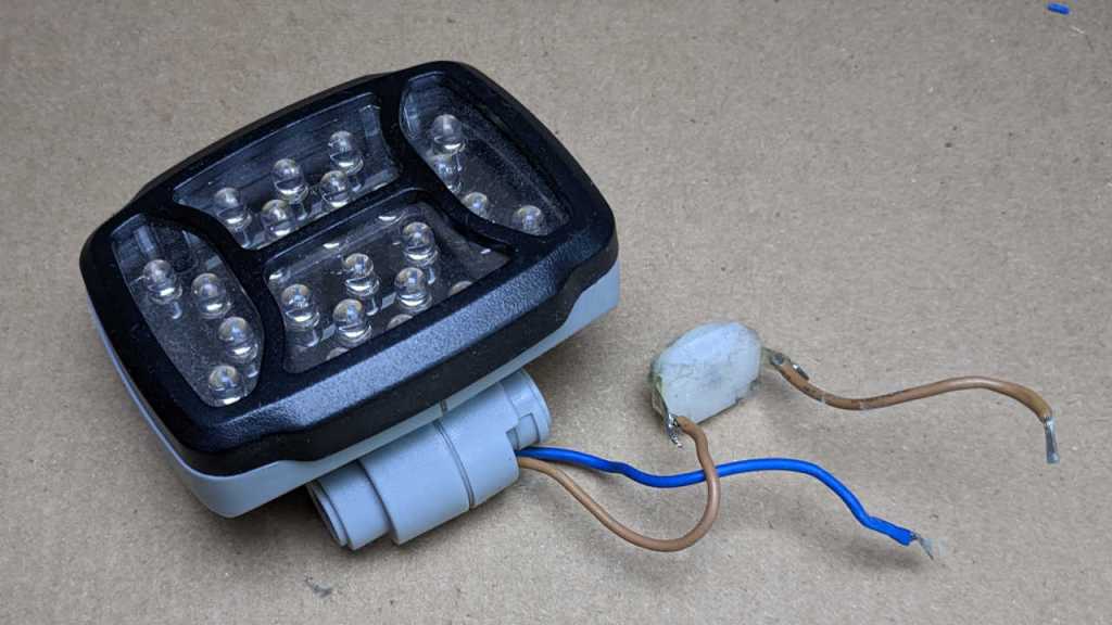
I think there was only a single fastener involved in this LED array, and it was already gone from teardown earlier so now everything slid apart easily.
I like the LED housing and intend to use it, but I wanted to take a closer look at the LED array.

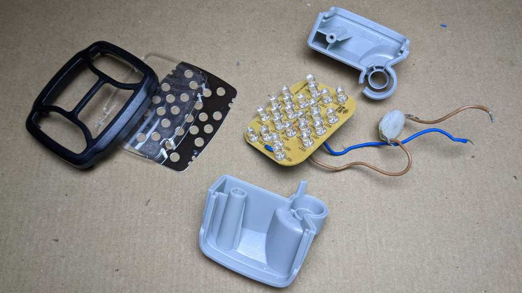
I confirm the 24 white LEDs visible before disassembly, and there's nothing else hiding on this side of the board, just the power supply wires looping through for a bit of strain relief. We can also see that Chervon Group was the subcontractor who produced this device to be sold by Sears under their Craftsman branding.

Everything is on the backside of this circuit board. From here we can see the 24 LEDs are arranged in 12 parallel sets of 2 LEDs in series, each set with a 240 Ohm resistor between them. Beyond that, to lower left I see a cluster of components and I'm not sure what they do. My best guess is battery over-discharge protection. Perhaps the component marked ZD1 is a Zener diode to detect voltage threshold, working with power transistor Q1 to cut power if battery voltage drops too low.
The most important thing is that I don't see a microcontroller that requires time to boot up. I will be pulsing this LED array rapidly and want minimal delay between power and illumination. If delay proves to be a problem, I'll try bypassing those lower-left bits: Relocate the power supply wire (brown wire, connects between markings R1 and ZD1) so it connects directly to the LED supply plane. Either to the transistor tab adjacent to the Q1 marking, or directly to the high end of any of those 12 parallel LED strings. But I might not need to perform that bypass. I will try my experiment with this circuit board as-is.