RGB LED Fan Hub and Remote (Asiahorse Magic-i 120 V2)
I bought the Asiahorse Magic-i 120 V2 package from Newegg, which bundled three 120mm fans with embedded RGB LEDs with a hub and a remote to control those LEDs. Now that I have successfully created a control circuit for my own independent control of those fans and their LEDs, I no longer have any use for the hub and remote.

The remote has an array of 21 membrane buttons. Across the top, we can turn the LEDs "On" and "Off". "Auto" will start running an animated pattern. Just below the "Off" button are brightness controls. S+ / S- controls the speed for animations, and M+ / M - cycles through different animated patterns. Bottom 12 buttons will show the selected solid color.
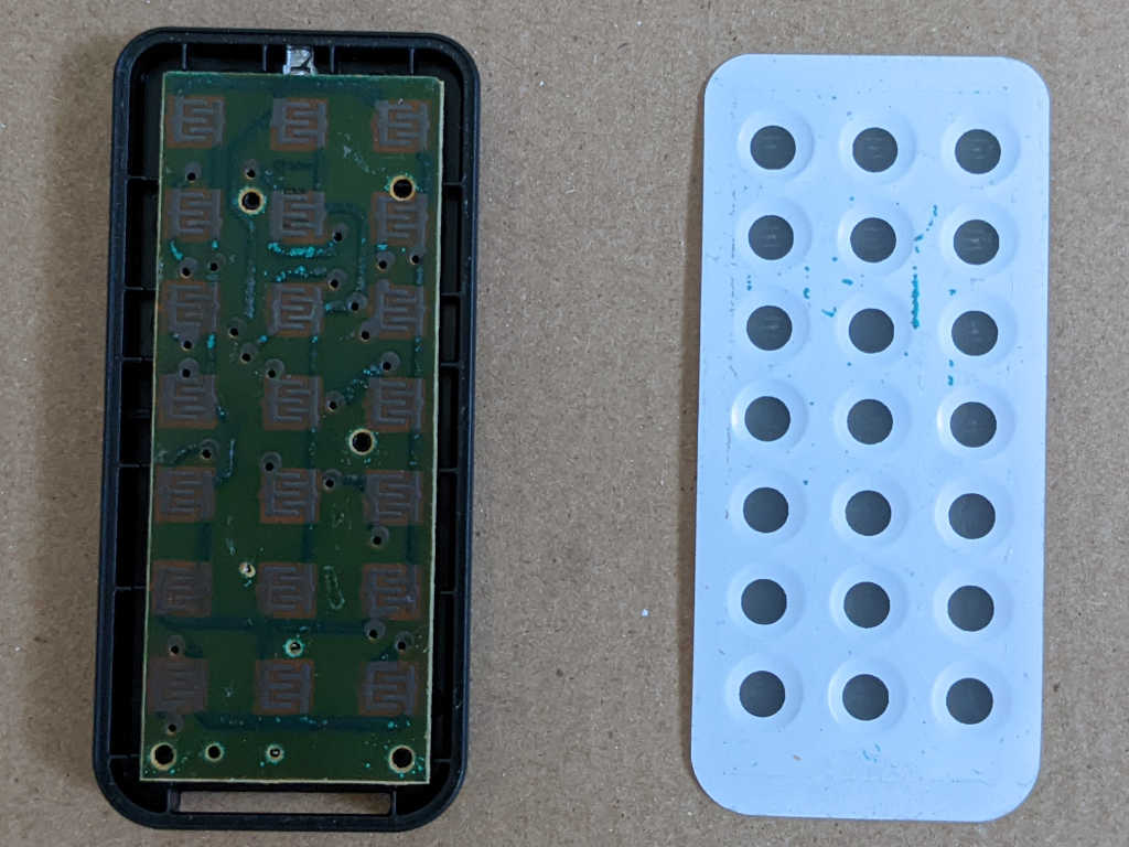
Top membrane is held on with moderately strong adhesive that could be peeled off, exposing the less interesting side of its circuit board.
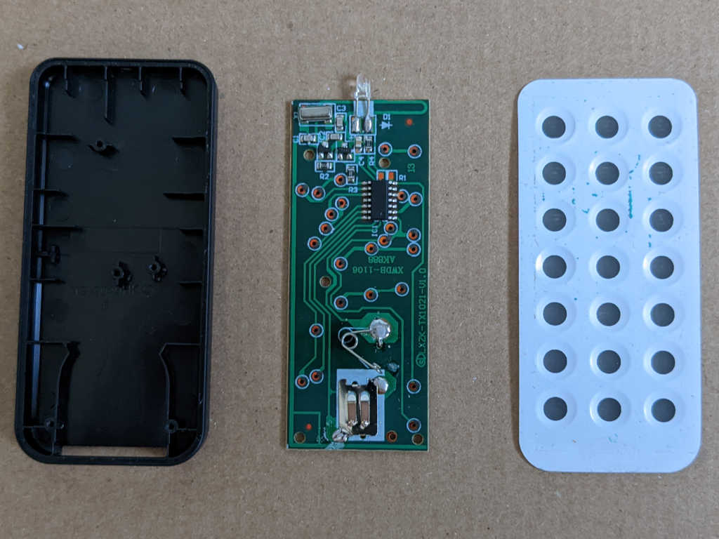
Flipping the board over showed a single chip with its support components. There were no visible markings on the chip. Battery contact springs are at the bottom, the top features an infrared remote control LED emitter, and a few passive components in between.

After disassembling the remote, I started on the hub.
There were no exposed fasteners top or bottom. I pushed on the bottom sticker and felt the corners move.
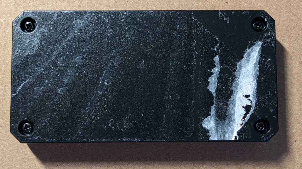
The bottom sticker is glued on more tenaciously than the remote membrane keyboard and refused to come off cleanly. But at least those four Philips head fasteners are now exposed.

Not much to see on the bottom.

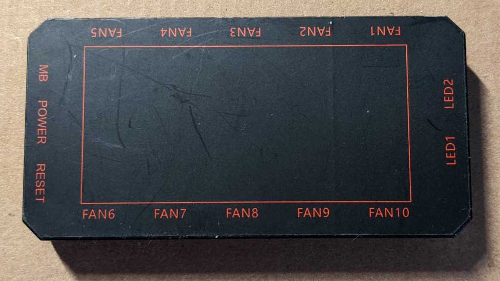
Flipping the circuit board over exposed... not many more chips than the remote. Most of the surface area are consumed by connectors all around the perimeter, and traces to connect them.

I'm glad to see fan connector pin labels are consistent with my reverse-engineered pinout table. A large component on this board appears to be a power transistor. I probed its pins and one of them is connected to all "F-" pins, so it is present for fan control. There are three sets of unused pads across the middle, provision for WS2812 LEDs wired in parallel with the fans. These three are chained together, left-to-right, with the leftmost LED receiving the same "DI" (data input) as all fans. When present, these three LEDs would act identically to first 3 out of 12 LEDs on board each fan.
There were a few other unpopulated pads on this circuit board, but there is one part I found fascinating for its absence: an infrared receiver like the one I found in a Roku. I don't see one, and I don't see solder pad provision for one. How could the hub receive IR remote signals without one? I know the remote and hub works together, so does this mean they communicate by radio frequency instead of infrared? I don't know enough about RF circuits to look for components that would implement such a thing. I had thought all RF devices sold in the United States are required to have an FCC ID printed on it, but none are visible. Perhaps certain unlicensed frequency bands are exempt from FCC ID requirement? Shrug, doesn't matter to me anymore as I won't be needing this remote or hub to put their associated fans to use.