Exploring 6-Wire Connector of Asiahorse Magic-i 120 V2
I was curious about PC accessories with embedded addressable RGB LED, so I bought the cheapest item available on Newegg that day. I have verified it works as originally intended, and now I'm going to dig deeper. This Asiahorse Magic-i 120 V2 is a three-pack of 120mm fans with integrated LEDs. All three fans plug into a hub that has a corresponding remote control for me to select from a list of programmed patterns. This bundle is fine if I'm satisfied with those patterns, but I want display patterns of my own.
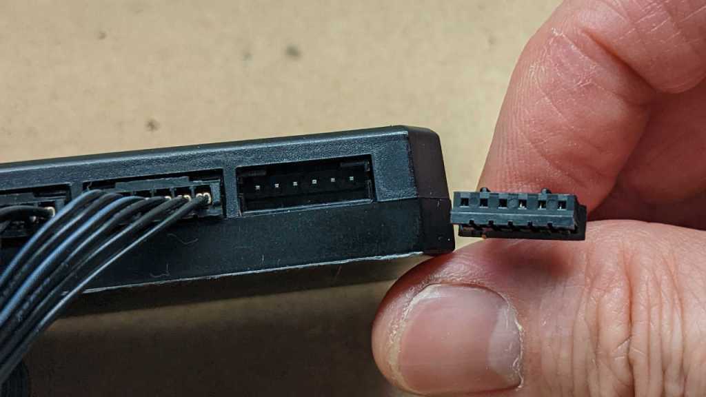
Each fan connects to the hub through this six-wire connector. The distance between each pin is 2mm. Judging by the pitch and physical appearance, I guess they are JST-PH or a clone. (I don't have any 6-conductor JST-PH to verify.) This is mildly inconvenient because my workbench is setup to work with 0.1" pitch (~2.54mm) connectors so it's not very easy for me to probe those signals as-is.
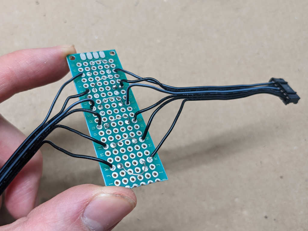
The solution is a quick soldering project to give me an exploration board. I cut the bundle of six wires and inserted a small piece of perforated prototype board. Each of the six wires are then bridged with an exposed length of solid wire, easy for me to clip probes onto.

Trying the easy thing first, I probed for continuity between these six wires and the power input wires. This gave me location for +12V source, +5V source, and ground. Armed with this information, I soldered capacitors to smooth out both power rails, because the AC adapter I'm using is designed for far higher wattage than a few LEDs and it's not unusual for switching power supplies to be noisy at low power levels. (And the cheap ones are always noisy at all power levels...)
With three out of six wires identified for power, this left me with three more wires to decipher. Here are my candidates:
-
Fan control: it may be one (or none) of the following:
- Fan motor high side: the fan may be internally connected to the ground wire, and the high side wire is left exposed here for external PWM or on/off control with a power transistor.
- Fan motor low side: the same idea but reverse: fan motor is internally connected to +12V and the low side is exposed here for external PWM or on/off control with a power transistor.
- Fan motor PWM: Neither of the above. Instead of leaving either high or low side unconnected for external power transistor, a suitable power transistor is built into the fan and controlled with a 25kHz PWM signal as used in 4-wire fans.
- Fan tachometer like the type I found in 3-wire fans.
- LED Data In: addressable RGB signal input.
- LED Data Out: signal that has passed through the LED string inside this device and ready to be passed on to other LEDs in other devices down the chain.
To decipher which wires are which of those candidate capabilities, I connected my Saleae Logic 8 to the three unknown wires. I started an analog waveform capture session and used the fan remote control to command that all fans show a solid green.
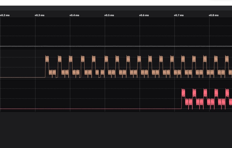
The top line in white stayed at 0V through the entire session. This may be the tachometer wire, or it may be fan motor low side. To determine which, I disconnected everything other than the +12V and ground wires. The fan did not move. I connected the wire corresponding to this white line to ground, and the fan started spinning. Conclusion: this wire is fan motor low side.
The middle line in brown shows a distinct repeating pattern. The bottom line in red shows the same repeating pattern, but delayed by 12 cycles. Since there are 12 LEDs in a fan, that means the middle brown line is LED Data In and the red line is LED Data Out.
To verify LED Data In, I connected +5V, ground, plus this wire to the data pin of a Pixelblaze. After I configured the Pixelblaze to emit control signal for a string of 12 x WS2812 (NeoPixel) LEDs, I saw them light up appropriately on the fan.
To verify LED Data Out, I connected it to the data input pin of an array of 64 WS2812 LEDs. I configured the Pixelblaze for 12 + 64 = 76 pixels. After colorful pixels cycle through the fan, they marched onwards to the array as appropriate for LED Data Out.
With these functions verified, I'm confident enough to describe this Asiahorse fan pinout.